Brief Introduction
Based on the obstacle listed above from both of my precedents, I decided to design a product that could solve problems such as transportations suddenly running out of fuels in pristine regions and could not be restored without finding a gas station, or electric-car charger. However, it seems like it would be impossible for me to design a huge product such as solar-powered transportation because of the limited amount of time. Thus, I decided to devise a mini-solar-powered vehicle model that spans about 20*10 cm, but would run the similar circuit that real-life solar-powered transportations acquires, in which the entire circuit would be powered by a 6v solar panel that would supply sufficient electric energy to spin the motor, thus motivating the rotation of the wheels.
Planning
Output (structure/looking):

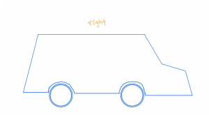
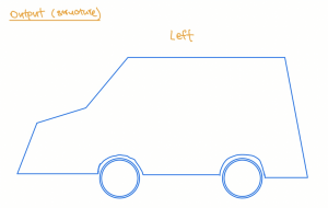
This is the overall structure of my car. I made it resemble a real-life car model. The vehicle has 4 wheels, and one pair of them would be powered by electricity produced by the solar cells on the 6v solar panel, which is located at the top of the vehicle. Thus, the pair of wheels that spins with the motor would then carry the other pair to rotate simultaneously, and in the same direction, to make the vehicle function. For each side of the car, I decided to make it a little bit creative, to make it aesthetically appealing.
Input (circuit):
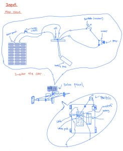
The input of the vehicle, frankly, is a simple circuit powered by the 6-volt solar panel. To be brief, the solar panel has 2 types of electric charges, positive and negative, and it would be connected to a motor through sophisticated wire-systems. Specifically, I decided to place a battery pack that could be filled with a maximum of 2 batteries, which acts as a storage battery in the entire circuit, with both of its wire connected to the board. After that, I must connect the positive charge of solar panel to another position on the bread board, and plotting the wire that connects the negative charger of the solar panel, and the 2 wires connecting to the motor in different directions since I must attach both of the plugs of the motor with a wire to let it rotate. Then, I placed a LED light with the longer strip dipped to a hole that is a hole left from the wire that connects to the positive charge of the solar panel, and the shorter strip 1-hole right from where the red wire of the storage battery is placed, and finally completing the circuit. If the volt did transcend, then the electricity from the battery would pass the bread board and flow to the solar panel, thus crashing the panel due to the enormous thrust generated, damaging the overall circuit. The LED light acts as a protector, or a resistance because it could halt the electric current from the storage battery surpass 6-volt, and thus avoid the solar panel from being ravaged. Also, these “equipment” must be stationed at the interior of the vehicle, or otherwise would make the model not aesthetically appealing. However, I recognized that without a switch, I might not be able to stop the motor from rotating, and so would affect the overall motion of the vehicle. Concurrently, I did not want the LED light to be always on since it always acts as a charger for the vehicle. As a result, as I’m planning, I decided to add a switch on one side of the motor that connects with 2 wires and repeated the same step by placing a switch between the wires attached to the positive charge of the solar panel and the bread board. Therefore, I could decide on when I would like to make the vehicle run, and when to fulfill its battery if the car suddenly runs out of it.
Main Engine: Motor


I decided to design the motor by using the idea of gear drive, an academic term that is being frequently used in mechanical engineering, in which a smaller gear (gear 1) would be plugged onto the tiny axis elongated from the center of the side surface of the 6-volt motor, then make the teeth of it loosely adhered to a bulkier gear (gear 2) comparing to gear 1 (gear 1 is thicker comparing to gear 2, and it probably allow more force to push the car forward to be exerted from the motor because a gear with analogous size comparing to gear 2 would add up the resistance). The hole in the middle of gear 2 is being pierced by a metal rod with each side of it attached to the front wheel of the vehicle, and by doing so supports, and promotes the back wheel to rotate with the thrust from the engine. In the discussion of automotive design, this is a type of dynamic distribution, which is as known as the front wheel drive. This specific type of dynamic distribution is especially useful for my vehicle model because power system is mainly concentrated on the front portion of the car, thus providing space for me to place the main circuit at the middle-back portion of the vehicle, which is a lot of space. Concurrently, it provides the car sufficient electricity to power-up the motor, and makes it function efficiently, thus making my vehicle run.
Leave a Reply