Engineering Blogpost #3

Design class #1: I focused my time this lesson entirely on the template of the car since the chassis and body of the car are to be laser-cut. I also gathered some of the materials needed (skewers, straws) and inquired about the 3mm plywood and laser-cutting machine.

In the initial draft for the template, I focused on recreating the general shape of the car.
Finished template layout

Design class #2: I prepared the finished template for laser printing by rearranging the pieces. I decided to print out the chassis and sides only to test the skewers and elasticity of the rubber bands. For me to be able to test the prototype, I used wood glue to stick the pieces together. I learned that I should use painter’s tape to temporarily hold the wood pieces in place and for the wood glue to set.

I marked the areas to cut the straw/axle holders as well.

Prototype pieces that were cut out and stuck together with wood glue.
Top view of prototype.
Prototype with axle holders (straws) installed, not cut.

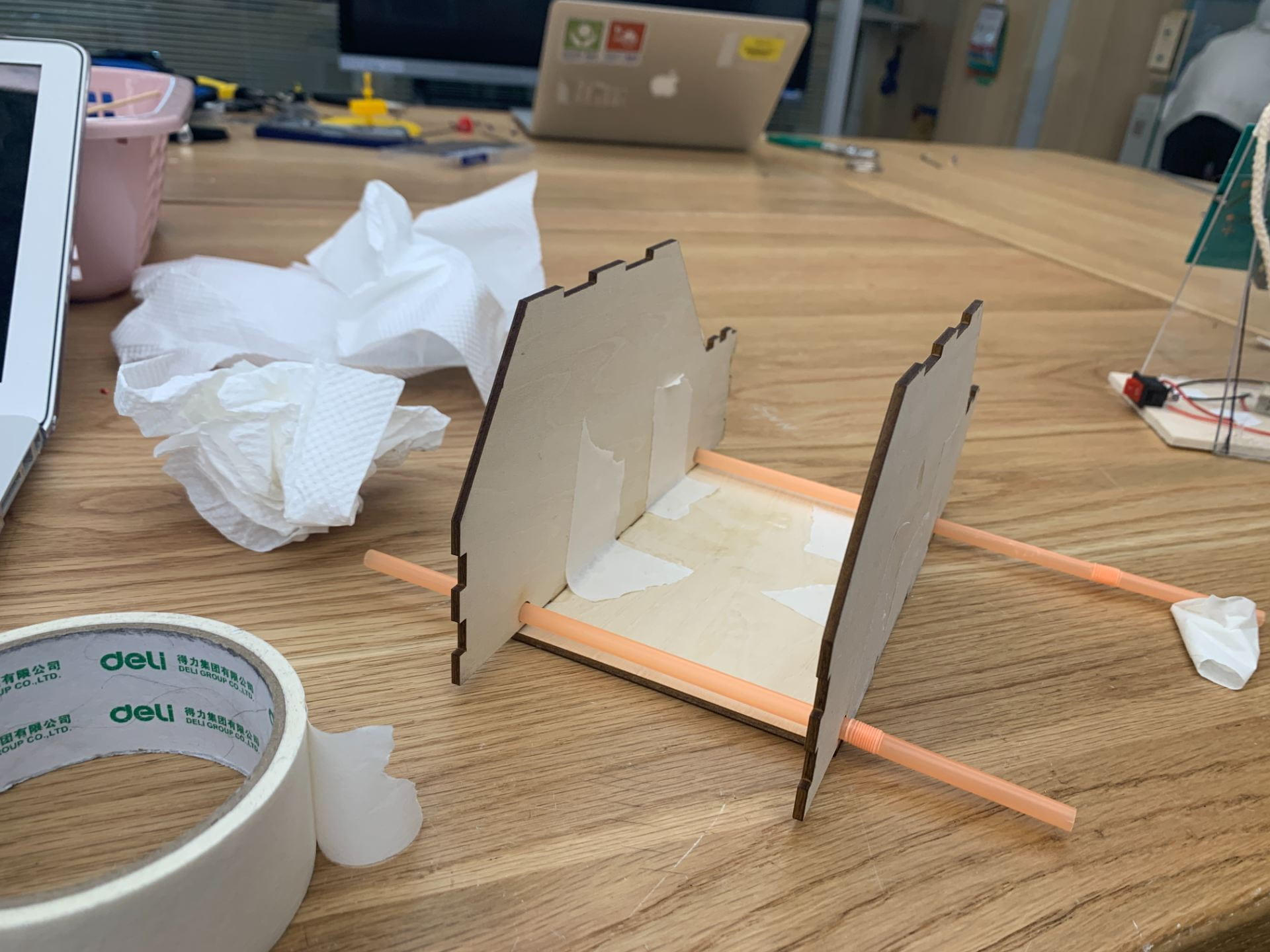
Design class #3: I finished up the 1st prototype by cutting parts of the straws off to hold the axle as well as cutting off parts of a skewer to act as an axle. After that, I have used hot glue and painter’s tape to secure the elastic band onto the body and the back axle. I have decided to not use a dowel/skewer to hold both ends of the rubber band. Instead, I will glue the rubber band directly on it.

I used painter’s tape to attach the elastic band to the body so I could experiment with placing the elastic band on different parts of the body.

Top view of completed prototype #1.
Another view of the first prototype. Note that the side pieces are bent.

IMG_3062 (Link to a video of the first prototype being tested)

Design class #4: Because of the 1st prototype not being cut properly (and after feedback given from peers in regards to the bent sides), I decided to laser cut all of the pieces again, including the bumper, hood, and top piece. Because there was a queue for the laser-cutting machine, I waited for most of the class to get my wood pieces cut. I also used wood glue and stuck the pieces together.

I dismantled parts of my 1st Prototype to measure the skewer length and straw length and make adjustments from thereon.

Picture of the body of 2nd prototype.
Photo of the 1st and 2nd Prototype together.

Design lesson #5: Parts of the body of the 2nd Prototype did not stick properly. I spent some time regluing certain parts of the car. I’ve also noticed that I have miscalculated the length and width of the car, resulting in the inaccuracy of some parts. I attached the rubber band to the back axle, but I did not have enough time to finish the front axle and attach wheels onto the car.

If I had more time, I would finish attaching the wheels to the car and then thoroughly test it out.

Front view of the 2nd prototype.
Close-up of the front. As you can see, some parts are misaligned.
Back view of the 2nd prototype, showing the back axle in place.


Engineering Blogpost #2

Sketch/plan of the product

For the Engineering project, I decided to make an elastic-powered car with a 3-millimeter thick wood laser cut with extruding parts to allow for me to apply adhesive to stick the pieces together.

Techniques I will need to master:

One of the major components of my project is the laser-cut body, so I spent a lot of time manually drawing out the lines from scratch to cut and to ensure that the parts are cut at the same length in order to fit in together. I decided to use Adobe Illustrator to design the body of the car due to me being somewhat familiar with the software. If help is needed with the laser-cutting portion of the car, I can search online and consult one of the design facilitators on laser-cutting.

After all the parts are laser cut, I will need to stick the wood pieces together. I plan on using wood glue, which works well with flat, 90 degree corners in a staggered pattern (see sketch and adobe illustrator picture). I have used wood glue in the past during Grade 8 Product Design to stick together a laser-cut box, therefore I feel that I should be able to use wood glue effectively. If I do run into trouble using wood glue, I can consult the design facilitators and they can give me advice on the usage and application of wood glue.

I will also need to use hot glue in order to apply the dowels/columns that hold the rubber bands in place, which I can do by practicing using the hot glue gun or with help from my colleagues. Previously in Grade 8 Product Design, I have used hot glue therefore I feel that I will be able to accomplish using hot glue in my project.

The laser-cutting template as seen on Adobe Illustrator. Text included is for measurement reference.

Materials needed:

  • Skewers to act as axles (Confirmed)
  • Straws to hold axles (Confirmed)
  • 3mm Plywood for the body of car (To be confirmed)
  • Laser-cutting machine to cut wood (Confirmed, need to send parts in advance)
  • Wood glue (Confirmed)
  • Hot glue (Confirmed)

Timeline:

Lesson 1: Inquire into materials, start designing laser-print template

Lesson 2: Finish laser-print template, start laser-cutting

Lesson 3: Finish 1st prototype, re-print parts (if needed), ask for feedback

Lesson 4: Start final product assembly

Lesson 5: Finish final product, test product


Engineering Project Blogpost #1

So far, I wanted to make some sort of contraption or toy that can allow younger kids to learn and understand energy transfer. I had difficulty coming up with some ideas, but here are some of them:

My first idea is basically a windmill that is spun by the cranking of a handle. Here is a diagram of something similar to my idea that I’ve found online:

Model of a windmill similar to what I envisioned with a handle to crank the windmill

Some pros of this design are that the design may not be as difficult but would require woodwork and that the design effectively shows the energy transfer from the cranking of the handle to wind energy from the movement of the rotors. A con of this idea is that this idea may be too simple and easy to make.


Another idea I have is somewhat the inverse of this idea, where via a source of wind energy, rotors on a windmill are spun and possibly some contraption that moves and as a result of the spinning of the handle links to the contraption, leading to the contraption making some movement as well.

Instead of having a person cranking the handle of this contraption I made in Grade 6, perhaps I could attach it to the handle portion of the windmill above and use wind power to move a similar contraption.

Some pros of this idea are that this is a variation upon the idea of the crank windmill and this makes it a bit more advanced than the previous idea, which may be beneficial and not as beneficial. This idea is also good to show how the energy transfers from wind energy to kinetic energy from the movement. Some cons of this idea are that this idea may take more time to build and that this idea may not be the most original.

Some other ideas I have that I have not explored as much is the option of making some sort of toy that relies on elastic energy that converts to create elastic energy, such as a toy car that will drive forwards after being pulled back.

My Cranky Contraption

Overall, I think this product was successful because…​

I think this product was successful because I managed to make a cranky contraption that can successfully function normally but with an added theme.  The theme I included here is a police officer because my client for this design is a police fan. My client is one of my friends from my old school BSB, but now he is in Canada. I still have contact with him, but I want to make a cranky contraption for him because he has played a role in my life.


One thing I’d like to change is…​

One thing I’d like to change is I’d have the proper colors of a police officer. I have accidentally mistaken dark blue as black, therefore it doesn’t look as realistic. A normal police officer has a blue shirt and maybe black pants (which I have accomplished successfully). Another thing I would have changed is to have the paint to be done properly. When I have done the painting, because of the lack of time I painted directly on objects even when they are not dry, causing it to have lower quality.


My biggest obstacle was…

My biggest obstacle is that I want the arm to go high up. At first, I thought to put the linkage nearer to the right side of the arm, but that just resulted in the arm going very down. Therefore I reversed and made the linkage go through the arm more closer to the left, which results in the effect I have now.


Save the penguins & Cup Insulator

For the Save the Penguins dwelling and Cup Insulator, I am very proud of how I overcome my fear of hot glue and used it myself (however very badly)!

I would improve my insulator more by design and layering to prevent heat if I would do it differently and reduce thermal energy transfer. I would make the cup less floppy and have a option to have the cup or remove the cup.

The cup quality is not bad but I realized that the hot glue for the mouthpiece melts and will not be good when someone is drinking the water. This will cause complaints if it is actually marketed. There are random pieces of hot glue on the prototype and the insulator is not waterproof.

Penguin Dwelling
Storyboard
Insulator on the cup

‘Survival’ challenge

In science, we did a design challenge and designed a water filterer. We planned, built, improved and tested our prototype. It was fun! After the test, we found out our water is clean, but not SUPER clean. We can’t drink the water anyways!

This is my prototype for the design challenge