Steven's Blog

Nothing is free-"Steven"

Category: DESIGN

Science Engineering project blog post #4-Reflect and Share

Images and videos of the final project:

I have now attached everything and essentially completed my final step in my design, now I just need to tweak and make adjustments to the angle of rotation and the speed at which it is spinning, all to better suit the purpose and design of this project. The video is attached here.

Here is the grande final version of the project; this video was filmed in school and demonstrated how the mixer worked. Mr. Hussack gave a fantastic idea to employ food color to show the “mix,” as can be seen in the video here. It was honestly both shocking and extraordinary to see it work so amazingly!

Here is the link to the one drive folder containing the design process of this product and all the videos shared.

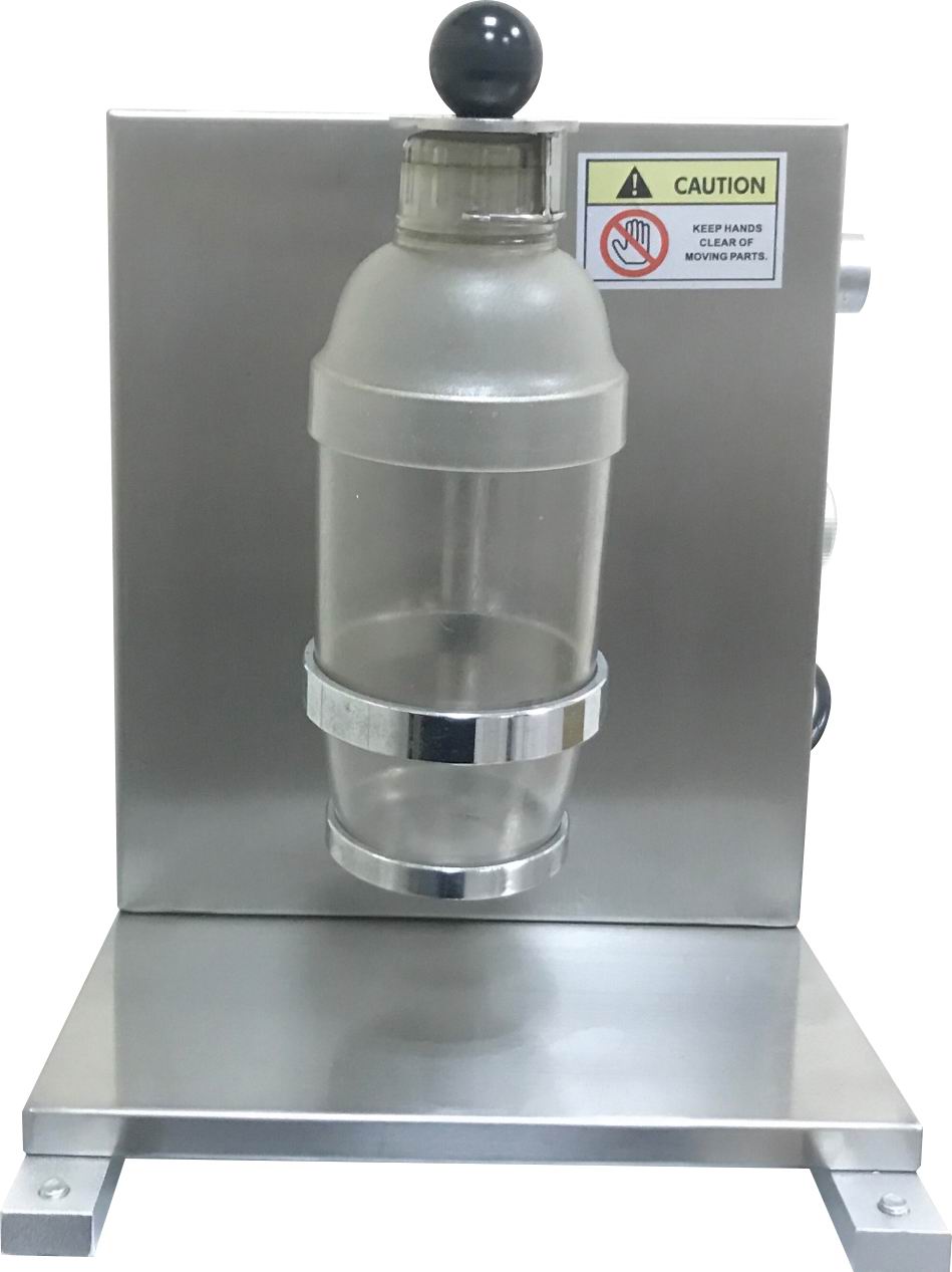
The science behind all this that allows the project to work is relatively straightforward and relates to the transfer & movement of energy. As the motor is electrical and needs electricity to function, the principal and only energy source are the six AA batteries that power up the motor, which then spins the wooden platform and consequently spin and mix the cup. The flow of electricity travels around in a loop or a circuit that maintains the balance of the negative and positive charges; it is constructed so that the negatives and positives do not intersect and therefore do not create a short circuit. The switch acts as the circuit “gate”; it allows electricity to flow through once opened and ceases electricity flow once closed; this is greatly necessary to control the motion of the motor, or else the motor will constantly be spinning. Furthermore, chemical potential energy is stored within batteries, and electro-mechanical devices, such as the rotation motor, convert the energy transferred from the batteries into motion. When the motor is spinning, electrical energy is constantly converted to rotational motion, which then outputs to the wooden platform, turning the cup.

In my opinion, the most prosperous area in this project was designing the product, applying feedback, and making changes along the way, essentially the “create and improve” process. It is undoubtedly normal to make mistakes and face challenges during the process of designing; however, I believe it is vital that we take the time to reflect upon our work and, most importantly, ask & take in feedback from others, ultimately applying those and make corresponding changes. When I encountered challenges, I reached for help from my peers and adults, received their feedback, and used their suggestions for my own project. This, I believe, was a strength of mine as I was able to significantly improve my work and reflect upon my error,; correct them, and enhance them. Moreover, I successfully designed the motor placement and its connection with the wooden platform. I specifically made the platform attached at an 80-degree angle so that the cup, when spun, will create a whirlpool effect that, to a large extent, helps the “mix” of the liquid. This unique detailed design turned out to be very successful and efficient.

An area of improvement is definitely the aesthetics of the project; although it functions well, it simply looks too pale and “ugly.” I always plan to decorate the foam box with colors and papers once I complete the electrical and “essential” parts. However, due to time constraints, I did not have the opportunity to do so. Again, this is my personal mistake as I should not have spent the first three classes working on a project that did not function, but instead, I should plan my time and project wisely and more productively in the future.

This project primarily aims to help people who require a machine to automatically mix/shake a liquid (most cases a drink) and generally people who are causally in the kitchen, making food, drinks, etc. The project’s theme is focused on relaxation and enjoyment and comes in handy by saving time and unnecessary actions, as the machine will do it for you. Not only does this project target family-based consumers, but also possibly industrial clients, who require large amounts of work without the need for human power. This project clearly saves people’s valuable time and efficiently produces, with quality, the drink or liquid substance they require. Additionally, apart from the styrofoam box that was supposed to be wooden, the materials needed to create this project are environmentally friendly and sustainable, providing a valuable machine to society while remaining eco-friendly. This makes a general impact on the environment as more consumers and clients are willing to use this design. We live in a world in desperate need of environmental protection and the sustainability of our earth; eco-friendly products will be higher in terms of demand in the market, followed by a possible higher output price.


Science Engineering project blog post #3-Create and Improve


Design class #1 This is a picture of my collection of *starting* materials, including the AAx6 battery pack, electrical rotation motor, suction cups (always kept spares), servo tester, a level switch for testing, and an Arduino in case I needed to code & program. Note that the rotation motor here is black and differed from the blue one; this was the one I began to use first but was later switched to the blue one (see picture below) due to its heavyweight and size.

Design class #1 This is when I collected all the materials and started my first test run of the motor, with the rotation motor (black in the picture but was later changed to blue) connected to the battery with alligator clips. The trial run with the black motor was reasonably successful and the motor functions well. In the meantime, Mr. Costa, a design assistant in the engineering space,  suggested I use a much smaller rotation motor (as can be seen on the left of the servo tester); despite its size, it was particularly potent-even more powerful than the previous black one! Applying the feedback from Mr. Costa, I then changed from my original motor to the blue one; it turned out to be exceptionally useful and provided immense strength. Thanks, Mr. Costa! (The blue motor was tested outside of this picture. Unfortunately, the photo of the blue motor being wired to the system was not taken, but it is essentially the same circuit, only replacing the blue motor with the black.

Design class #2 Here is the “light switcher” I have made from a 12cm long wooden stick and the hard-plastic motor connector piece attached to the front +/- 2cm of the tip by hot glue. This will be attached to the blue rotation motor by placing the connector piece onto the motor attachment place. I have done multiple tests for secureness, and I am definite that the wooden switch will stay in place during the spinning motion.

Here is a demonstration video to observe the motor turn with the wooden switch attached. I have also shown how the servo tester can control the speed at which the motor is turning and its spinning direction. I apologize for the video exceeding the upload file limit on blogs and have shared it in a one-drive folder instead.

See the source image

During design class #3, it was heartbreaking and unfortunate to encounter serious difficulties and errors in my project. It turns out that despite the abundance of power I believed the blue motor had, the power at which the motor is spinning the wooden switcher was, in reality, way too low to even turn the light on. As a result, it would simply hit the surface of the light switch at a fast speed; however, there is not enough force to “click” the switch. This was generally my mistake, and I definitely should have considered this more in-depth into this particular aspect before I did the project. This is an excellent lesson to learn and will be nevertheless reflected upon, and of course, taken into consideration for awareness and changes for future projects.

(This was done outside of class) Moving on from the first idea that was unfortunately unsuccessful, I have made the decision to develop a project based on the previously mentioned idea “electric cup mixer & shaker.” I included a materials list in the picture above. As you can see, I wanted to utilize as many as possible resources that I had already collected in my first idea. That way, it saves me valuable time as I can reuse these same resources. Given its name, my new project was essentially a cup mixer that targeted and aimed to help people making drinks who are in a kitchen area. The machine will be operated under electricity, more powered explicitly by a six AA battery pack connected to a 360-degree rotation motor. The entire project will be set on a 20cm long, 15cm wide, and 15 cm tall foam box, with the motor hidden and inside the box leaving only the wooden cup-holder platform on top, and of course, the switch to control the flow of electricity. I have specifically designed the wooden cup-holder platform to be 8cm by 8cm. Therefore, the 5.5cm popsicle stick panels will *securely* hold the majority of all cups, bottles, and can types. -Every bottle/cup I have seen and tested so far fits perfectly except those Camelbak wide ones. The mixer project can be controlled and used very easily; all the user/audience has to do is cautiously place the cup into the secure panels on the wooden platform and simply turn on the switch. The cup should “slide in” and secure on itself; I have purposely designed an elevated angle for the ease of the user and to prevent errors with the cup sliding out.

One concern I had for this new project was the balance and weight distribution of the base. The quick rotations of the cup when it is “mixing” might cause the entire foam box to flip over or become unstable to the ground. A solution to this would be to increase the weight of the platform and the amount of liquid there is inside of the cup, setting a minimum weight (volume) for the mixer project to work efficiently. This number will be around 40-50 ML as the minimum volume of the liquid in the cup.

I plan to finish my second project by March 7th. A new timeline is as follows:

Design class #4 Match 3rd, work on cup mixer project, and ask for feedback from teachers and design assistants

Design class #5 March 7th, finish up the project and finalize it, must apply the feedback given and make changes

The techniques I will need to learn in my mixer project remain the same; learning the fundamentals of electricity as well as circuits & wiring.


Design class #4

This is my sketch of the cup platform. It was then marked on a 1cm thin wood and lasercutted in the fab lab.

Here is the 360-degree rotation motor being tested; it is the yellow rectangular object below the yellow plastic wheel. I used the wheel at first, but it was suggested to me by my table partners and design assistants. My original plan (see picture 4) was to directly attach the cup-holder platform to the motor; however, when it was attached, it caused too many contacts with the foam surface and produced way too much friction for it to run at an appropriate speed. Connecting the wheel allowed space between the foam and the wooden surface and worked much more efficiently. The feedback was instrumental and beneficial in my process of designing.

Here is the 20x15x15 foam box. The inside was slightly different from the planned sketch but did not affect my project in any way. When I first designed the project, I was being extraordinarily foolish and absolutely forgot about the thickness of the foam-upper surface and that the motor’s pivoted axle would not even reach up to the surface, it can be pictured as a turtle trying to extend its head out of its shell but gets stuck midway. From another discussion with the design assistant, I was given feedback and advised to cut the styrofoam so that the motor can extend its “turtle-head out.”  As can be seen in the right-side picture above, I marked the area based on the dimensions of the motor and “dug” out styrofoam, making space for the motor to perfectly fit. This eliminated the error in my plan and was practical, realistic and straight to the point.


Design day #5

*Note-The plastic wheel is hot glued to the wooden platform

I originally planned for five popsicle sticks for secureness; however, during my process of making, I realized that an extra would be completely redundant and unnecessary. As I have tested, four wooden panels work much better than five and secure the cup efficiently. Along the process of designing, I also learned the technique of hot gluing. Of course, I have hot glued before, but this time, it was to a much greater extent; I had more practice with the glue gun and was able to better control and use the glue gun effectivity towards the project. In the beginning, I remember constantly overusing/producing glue and having to redo my work. Still, as I obtained more and more practice, I learned the necessary skills of hot gluing and applied that to my project.

Here is when I combined the two components together, not by hot-gluing but by using the “click” mechanism of the wheel to the motor. The motor has a concave indentation that perfectly fits the “ridge” tip of the wheel, making a “crack” sound and locks in, like putting together lego pieces. Note that the switch has not been attached yet and the project still remains on a motor-testing basis. The mixer & platform did spin in the way as planned, and worked very well to my surprise.

Here is an overview of my prototype, it is still in the testing process that’s why I used dual AA batteries instead of six.


Weekends non-school workday:

Here is the bottom view of the product, as you can see the switch is in place and connected, I have also made holes in the foam to pass through wires and tape to secure the wires as well. The battery is not attached in the picture but is in this demonstration.

Science Engineering Project Blog Post #1- Define and Inquire

Define the project:

This engineering task is to create an original project that both aids and helps a targeted audience and demonstrates scientific understanding, such as movement/transfer of energy. The task is aimed to be useful and purposeful, contributing to the world and most importantly original and aesthetically appealing.

Possible ideas:

-Portable suction light

-Magnetic/Hydraulic lazy tools-automatic movable shoulder rests, leg movers, arm stands, etc.

-Electrical automatic motorized light switcher (switches lights off from a distance (wireless/wired to be determined) without physically pressing them)

-Electrical motorized drink/bottle shaker

I am really interested in making the portable suction light, as it can be extremely useful for a variety of people and can be affordable, realistically made at the same time. On the other hand, the electrical light switcher is a unique idea, however, the level of difficulty to make the project work effectively is quite high.

KS-01 SINGLE BOTTLE FULLY AUTOMATIC SHAKING MACHINE | 台灣鎧瑋封口機How to Adjust a Lazy Boy Recliner Footrest: The Definitive Guide - Krostrade

Targeted Audience:

The suction light is for users who are frequently traveling, outside, staying at home, working, and are in need of portable lights. The suction is designed to cope with multiple different environments while providing a sufficient light source. Similarly, the light switcher is suitable for users that are at home or at a working space, the automatic light switcher can come in handy when saving time or simply being “lazy” at home when we do not have to get up and turn off the light.

Some constraints and difficulties the suction light will experience is the problem of electricity, if it is run by batteries then it will lack the purpose of long-term lighting. An alternate solution would be to use chargeable batteries as an electricity source, however, this also comes to the problem with designing a more heavy and bigger light in terms of components. Knowing that the whole goal is to be portable, the larger light is not practical. As for the light switcher, a major problem would be the switcher falling off/detaching from the wall it is connected to, due to the pressure, humidity, surface, or errors in the design. Another problem would be the limited distance from the remote control to the light if it is designed to be wireless. A wired connection should not be a concern and run smoothly.


Sewable Electronics Project-Pin

  1. I made a pin of “Brawl Stars” -a modern game video game, since I really like the game and I enjoy playing it, therefore a Pin of the game really suits me.
  2. The other designs were simply too simple and unsophisticated, they lacked details and colors. I choose this design as the final one since it looked vibrant, had a variety of colors, and had a videogame logo I liked.
  3. I was proud that I was able to successfully light up the LED with conductive thread.
  4. To me, the “sewing” part was an entirely new thing to me, but as I practiced many times throughout the unit, I was able to efficiently use this skill in developing my project.
  5. Primarily, able to strongly secure my “Cinch” stitch was pretty hard, but we had a couple of practice classes and I got better at it over time.
  6. Important tip: Be CAREFUL when sewing, especially your fingers, hold your felt securely, and do not slip. Try not to poke the needle in them, ouch that hurts a lot!
  7. I want to learn a new series of stitches so that I can have a variety of techniques and ways of stitching in my future works.

App Inventor Reflection Blog Post

By Steven Chou 7-3

  1. I used to think that coding was very boring because it was just blocked after blocks of the same thing over and over again, but now I think coding is very fun and interesting because I could express my ideas and also get joy out of it.
  2. I built this app for Bryan.T because he struggles to keep track of his time while he is on a device. This app would help him keep track of his time and his eyes are more protected from getting myopia. (nearsightedness.)
  3. I designed the big countdown numbers at the top of the screen because that way it’s more visible and easier to see. I made the -/+ time buttons at the middle column because that way it was easier to press and click for the user(s). I made the meme buttons at the bottom because that way the meme pictures fitted the screen. Lastly, I put the “Go back” and “Credits” button at the bottom because that way it was more professional.
  4. The quality of the app is pretty good. The timer has simple buttons that have: “Start” “Pause” “Reset”. When you press to start the timer starts and obviously pause is pause and reset is resetting the timer. In the middle part, there are +/- 1 sec, 1min and 30min. When you click the button it will change the time on the timer. Finally, the “Credits” and “Go back” buttons take you to another screen when clicked.
  5. My app was very clear and easy to use. Users that use this app would know how to use it and understand it easily. However, this app does have some weaknesses.  The app is not very detailed in terms of button choices and looking.
  6. If I could redo this app, I would add more buttons to the timer and add more sophisticated, detailed, advanced coding to the app.

My advice for making this app: Focus on the coding first, then the decoration or coloring because you might run out of time later and you won’t be able to finish the app. Also, when you are testing your app, use a tablet and not phone because the tablet performs better and has a bigger, greater, clearer screen.

Click HERE to see a video of my app

Hummingbird Zoo Reflection

Sorry we forgot to take videos and pictures of the actual robot.

A part

1. The most difficult part of the project was when we have to attach the servo on to the side of the mouth. It was hard because we didn’t want to damage the Servo but we had to put hot glue on the servo. The Servo was also hard to attach because it had to be measure precisely and be glue on the cardboard sideways.-

2. The most enjoyable part of the project was when we finished the alligator and when it functioned. It was so exciting and happy to see the servo move regularly and function. We also had a feeling of” Finally!” In our thoughts.

3. I did well on making the servo and the hummingbird connecting together and working properly. Also, I did pretty well on the code part and the structure of the alligator.

4. I would paint and make the whole structure look nicer and cleaner. This is because our project now is very dirty and unorganized. It looks like everything is made and painted very roughly and without quality. So next time I would improve the quality of the alligator.

B part

1. I learn that fashion and style are not important in the process of making a working robot. The style and the colors, decorations come after everything is working and built. If the majority of the time is spent coloring and decorating, then the time to do the important things(servos, codes, structure) would be less. In addition, causing the work to be delayed or unfinished(not working)

2. When I was programming the robot, I learned that sometimes it is the hardware that isn’t working causing the whole robot to not work. Every time my robot does not function properly, I always think It’s my fault that I did the code incorrectly. But it was actually the battery pack’s problem; it was out of juice. As a result, I learned that I don’t always think I am the problem, I am always wrong.

3. I would like to learn about how to create a code that could let the robot be controllable with a remote controller. That way the robot would be more fun to play with and much more interesting to build.


My advice, recombination: Focus and try to finish the code first, then work on the body or the decoration of the robot.

My Cranky Contraptions

My biggest success was to create the up and down part for the Baseball/bat Cranky Contraption

My biggest obstacle was trying to make the head and the stick in position

Skills that I developed; How to make an up and down Cranky Contraption.

The Penguin Project and the Cup-Insulator project ( Save the Penguins )

This is our ( Me, Christian, Olivia,  Rachel’s ) Penguin Project.

The hardest thing about this project is the part when we have to create the penguin project. It was hard to make and the materials were limited, so we had some trouble with making.

I  proud of the measurements of the second test with our penguin project because the first one and the second had a major difference. That means we work really well on the second project.

I learned skills of hot-gluing and paper-crafting. I used to be really bad at hot-gluing but I improved my hot-gluing skills in this project.

A basic Reflection:

Day 1: We figured out what is Heat, Thermal Energy, Temperature.

Day 2: We did observations on different insulators and conductors.

Day 3: We made our first design on our Penguin Cup Design.

Day 4: We measured/test the first final design.se

Day 5: We made corrections and added more to the design and measured/test the second final design.

Day 6: We wrote the CER ( Claim Evidence Reasoning ) for every day ( all above ). We wrote the procedures for testing the design ( Steps 4-5 ).

My Self Saving water purifier project

Andrew and made this purifier. The challenge was to make undrinkable water into drinkable water on a deserted island. It turned out pretty good and the”Dirty water” turned out to be “Clean water.”

© 2025 Steven's Blog

Theme by Anders NorenUp ↑

Skip to toolbar